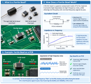
Ferrite beads’ primary function is absorb high-frequency noise on circuits.
Their core functions, key specifications, and common types are below:
Core Function: Absorbing High-Frequency Noise
The function of a ferrite bead is to eliminate high-frequency electromagnetic interference within a circuit.
Unlike inductors, ferrite beads are dissipative components, they convert high-frequency noise energy into heat and then dissipate it, rather than storing energy like inductor.
Equivalent Circuit: Can be taken as a combination of resistor and inductor in sequence, though both resistance and inductance values change with frequency change accordingly:
– At low frequencies, it is inductive, has minimal impact on the signal;
– At high frequencies, it is resistive, effectively absorbing noise;
Difference between Ferrite bead and Inductors:
Inductors store energy and typically use for low-to-medium frequency filtering;
Ferrite beads are dissipative, specifically designed to suppress and absorb high-frequency noise, and do not cause self-oscillation when used in conjunction with capacitors.
Key Specifications and Types
When selecting ferrite beads, we shall focus on the following parameters and types:
1. Key Electrical Parameters
– Impedance (Z): The core parameter of every ferrite bead, measured in Ohms (Ω).
It is usually specified by its impedance value at 100 MHz (e.g., “600Ω @ 100 MHz”).
Please note that this value is very important, but we should also consider the impedance-versus-frequency curve and understand it’s actual filtering performance across different frequencies.
– DC Resistance (DCR): The resistance of the ferrite bead for direct current, usually measured in milliohms (mΩ).
A lower DCR results in a smaller DC voltage drop across the circuit.
– Rated Current: The maximum current that is safe to flow through the ferrite bead.
Exceeding this value may lead to magnetic saturation, causing a sharp decline in filtering performance.
– Operating Temperature Range: Ensure the ferrite bead works stably within the circuit’s working temperature range;
Common ranges include -55°C to +125°C.
2. Common Types
Based on application scenarios, ferrite beads are primarily categorized to 4 types, as below:
– Standard Ferrite Beads:
Suitable for signal lines with low current (typically <600mA);
They generally feature DC resistance (DCR) in the range of a few tenths of an ohm and are used for general noise suppression.
– High-Current Ferrite Beads:
Specifically for high-current applications such as power lines;
They require very low DCR (typically <0.1Ω) to minimize power loss and voltage drop.
– Spike-Suppression Ferrite Beads:
Extremely high impedance for a certain frequency range, and very low impedance elsewhere (band-stop characteristic);
Use for the frequency-selective attenuation of noise at specific frequencies.
– Ferrite Bead Arrays:
Integrate multiple ferrite beads into a single package, making them suitable for high-density PCB circuits.
Experienced reference and suggestion for selecting:
– Rated Current:
Especially for power supply circuits, apply a 50% derating factor.
For example, if the operating current is 1A, select a ferrite bead with a rated current of at least 2A.
– Signal Frequency:
When used on signal lines, the ferrite bead’s impedance should be as low as possible at the operating frequency of the useful signal to avoid interfering with signal transmission.
– Filtering Requirements:
After meeting current and DCR requirements, select a ferrite bead based on the impedance-frequency curve, that matching the noise frequency band, rather than relying on the nominal impedance at 100MHz.
Summary:
Ferrite beads purify the current flow on circuits by converting high-frequency noise into thermal energy.
Nominal impedance is primiary to consider when selecting the suitable model, also a comprehensive assessment for the impedance-frequency curve, rated current, and DC resistance, that will help to select the right model and works fine on the PCB circuits.